
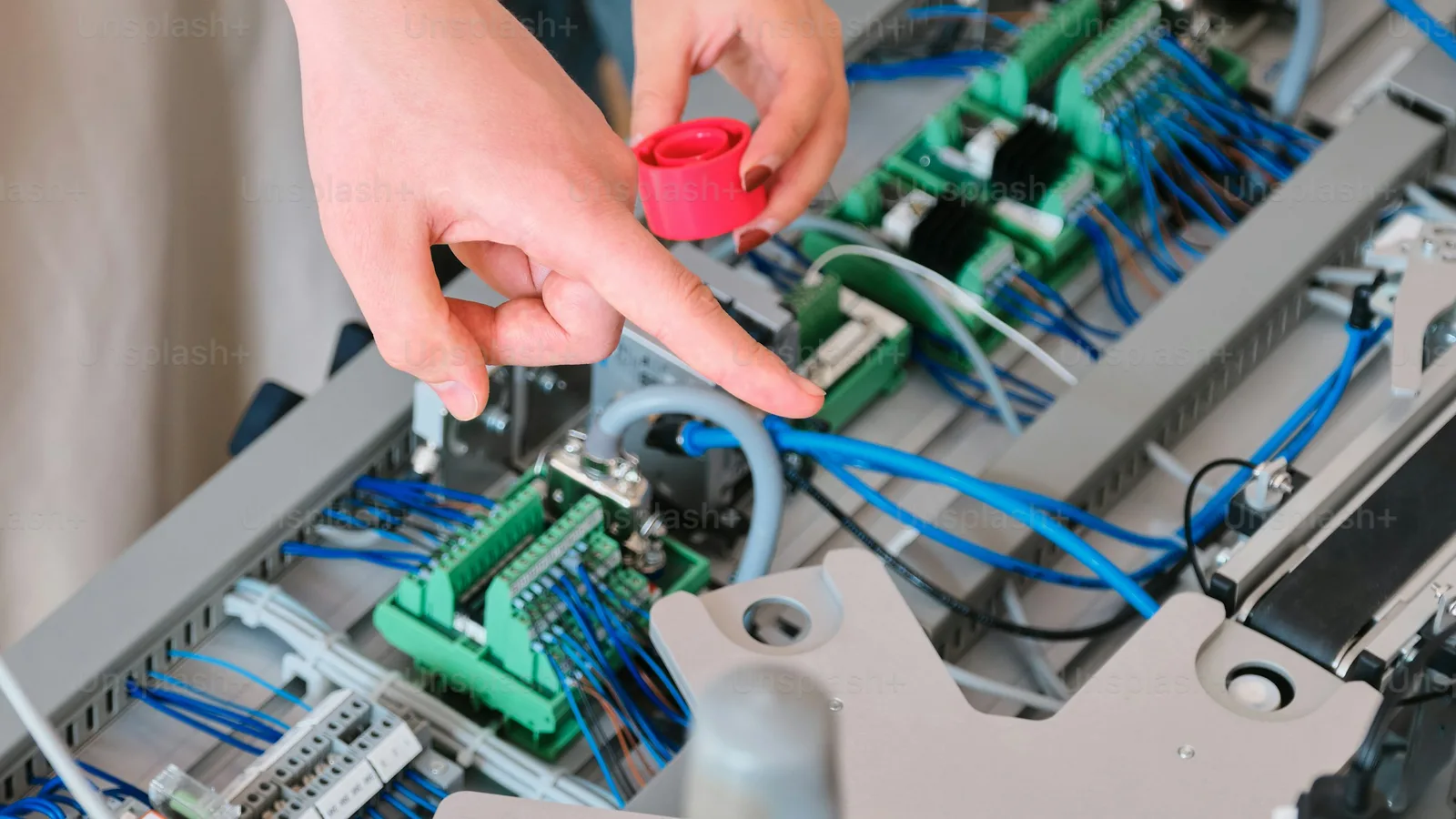
Panel Wiring Best Practices: Building Control Panels That Are Safe, Reliable, and Maintainable
Industrial control panels connect power distribution, motor control, PLC systems, HMI interfaces, safety circuits, and field devices. Panel wiring determines how effectively these systems can be commissioned, operated, inspected, and serviced.
A structured wiring method supports:
- Safe electrical operation
- Consistent machine control wiring
- Reliable conveyor control wiring
- Efficient troubleshooting
- Accurate future modifications
- Complete schematic documentation
- Compliance with applicable codes and standards
Conveying Controls L.L.C. provides control panel design, panel control wiring, schematic drawings, procurement support, FLA calculations, and PLC- and HMI-based automation services. More than 35 years of experience supports applications in manufacturing, warehousing, distribution, and material handling.
APPLY THE CORRECT STANDARDS
Begin each electrical control panel project with the applicable standards, project specifications, and local requirements.
Common references include:
- NFPA 70 : National Electrical Code
- NFPA 79 : Electrical Standard for Industrial Machinery
- UL 508A : Industrial Control Panels
- IEC 60204-1 : Safety of Machinery
- Manufacturer installation and wiring instructions
- Customer engineering specifications
- Authority having jurisdiction requirements
Standards affect:
- Conductor selection
- Overcurrent protection
- Grounding and bonding
- Enclosure construction
- Component spacing
- Wire routing
- Terminal connections
- Safety circuit design
- Inspection and testing
Use the current edition of each applicable standard. Confirm requirements with the responsible engineer, inspector, or authority having jurisdiction before construction and installation.
PLAN THE PANEL LAYOUT
Complete the panel layout before installing conductors. Component location affects wire length, heat management, accessibility, and maintenance time.
Organize components by function:
- Incoming power
- Main disconnect
- Circuit protection
- Motor starters and drives
- Control transformers and power supplies
- PLC and remote I/O
- Relays and safety devices
- Terminal blocks
- Communication equipment
- Field wiring connections
Maintain a logical relationship between the physical layout and the electrical schematics. A technician should be able to locate a device from its schematic identifier and trace its wiring without unnecessary searching.
Account for:
- Wire duct capacity
- Terminal block access
- Component removal
- Door clearance
- Cable entry locations
- Heat-producing equipment
- Bend radius
- Spare capacity
- Future expansion
Place cable entry points near the associated terminal blocks when possible. Position field terminals near PLC I/O connections to reduce unnecessary internal wiring.
SEPARATE POWER AND CONTROL CIRCUITS
Separate circuit types to reduce electrical noise, simplify troubleshooting, and support safe maintenance.
Use dedicated wire duct sections or physical routing paths for:
- Incoming AC power
- Motor branch circuits
- Variable frequency drive output
- 120 VAC control circuits
- 24 VDC control circuits
- Analog signals
- Encoder wiring
- Ethernet and communication cables
- Safety circuits
Avoid placing sensitive signal wiring in the same duct as high-current or high-frequency conductors. VFD output conductors can produce electrical interference that affects analog signals, communication networks, and instrumentation.
When conductors must cross, cross power and signal wiring at approximately 90 degrees. Maintain separation based on the applicable standard, equipment manufacturer instructions, and the project’s electromagnetic compatibility requirements.
Use shielded cable where specified. Terminate cable shields according to the approved design. Shield grounding requirements vary by application and signal type; do not apply a single grounding method to every installation.
SELECT AND SIZE CONDUCTORS
Select conductors based on:
- Load current
- Full-load amperage
- Overcurrent protection
- Voltage drop
- Ambient temperature
- Conductor grouping
- Insulation rating
- Enclosure temperature
- Installation method
- Equipment terminal ratings
FLA calculations support correct motor circuit design and protection selection. Review motor data, operating conditions, starting method, drive requirements, and applicable code provisions before finalizing conductor sizes.
Common industrial control panel practices include:
- Use stranded conductors for panel flexibility.
- Match insulation ratings to the circuit and environment.
- Use conductor sizes compatible with terminals and ferrules.
- Avoid overfilled wireways.
- Maintain required ampacity adjustments.
- Follow component manufacturer requirements.
- Verify voltage drop for long field circuits.
- Confirm short-circuit current rating requirements.
Do not select wire size from a general rule alone. Confirm each conductor against the complete circuit design and applicable requirements.
ROUTE WIRES CONSISTENTLY
Use horizontal and vertical routing paths. Avoid diagonal runs across the panel. Consistent routing improves identification and provides a repeatable method for tracing circuits.
Apply the following practices:
- Route conductors inside wire duct where practical.
- Keep wires clear of device faces and adjustment points.
- Avoid routing over terminal screws.
- Maintain smooth bends.
- Protect conductors from sharp edges.
- Do not force wires into undersized duct.
- Leave serviceable slack at terminals.
- Avoid unnecessary loops near components.
- Support external wiring at appropriate intervals.
- Keep spare conductors identified and secured.
Route each conductor from terminal to terminal without unnecessary intermediate splices. When a circuit requires a connection point, use an identified terminal block or approved device.
Keep wire duct covers removable without disturbing connected conductors. Maintain access to fuses, disconnects, relays, PLC modules, and terminal blocks.
IDENTIFY EVERY CONDUCTOR
Wire identification connects the physical panel to the schematic drawings. Mark conductors at both ends using durable labels that remain legible under expected heat, oil, moisture, dust, and chemical exposure.
Identify:
- Internal panel conductors
- Field conductors
- Terminal numbers
- Device designations
- Safety circuit conductors
- Communication cables
- Spare conductors
- Shield drains
- Grounding conductors
Use one numbering system throughout the project documentation. Ensure the same identifier appears on the schematic, wire marker, terminal schedule, and device label.
Color coding can support identification, but color must not replace conductor numbering. Establish the project color convention before wiring begins and apply it consistently.
Protective earth conductors require separate identification and handling. Do not use protective earth colors for control, neutral, or signal conductors.
COMPLETE SECURE TERMINATIONS
Termination quality affects panel reliability. Loose, damaged, or incorrectly sized terminations can cause heat, voltage drop, nuisance faults, intermittent operation, and equipment damage.
Apply the following controls:
- Strip conductors to the specified length.
- Prevent strand damage during stripping.
- Use ferrules where required by the terminal and project standard.
- Insert conductors fully into terminals.
- Tighten connections to the manufacturer’s torque specification.
- Use the correct screwdriver or torque tool.
- Confirm that no copper strands extend outside the terminal.
- Avoid placing multiple conductors in one terminal unless approved.
- Verify terminal ratings and conductor compatibility.
- Record torque verification when required.
Ferrules can improve stranded conductor termination by containing individual strands and supporting consistent contact. Confirm ferrule compatibility with the terminal design before installation.
PROVIDE GROUNDING AND BONDING
Bond metallic enclosure sections, doors, mounting plates, and other conductive parts as required by the design and applicable standards.
Verify:
- Main protective earth connection
- Grounding busbar installation
- Door bonding
- Enclosure bonding
- Ground conductor sizing
- Separation of protective earth and neutral functions
- Continuity across removable or painted sections
- Proper termination of shielded cables
Use protective earth conductors exclusively for protective grounding. Do not use grounding conductors as signal returns or control circuit substitutes.
Grounding and shielding practices must match the equipment design, control architecture, and electromagnetic compatibility requirements. Confirm the approved method before field installation.
MAINTAIN COMPLETE SCHEMATICS
Accurate documentation is a maintenance requirement. Comprehensive schematic drawings should reflect the installed panel, not only the original design.
Maintain current records for:
- Power distribution
- Machine control wiring
- Conveyor control wiring
- Panel control wiring
- PLC I/O assignments
- HMI devices
- Safety circuits
- Terminal blocks
- Wire numbers
- Device locations
- Network connections
- Spare points
- Component part numbers
- FLA calculations
- Revision history
Use device identifiers that correspond across schematics, panel labels, wire markers, and bills of material.
At project completion, provide updated drawings that incorporate approved field changes. Store documentation where maintenance and engineering personnel can access it.
INSPECT AND TEST BEFORE ENERGIZING
Complete inspection and testing before applying power.
VISUAL INSPECTION
Check:
- Component mounting
- Wire routing
- Wire duct covers
- Conductor labels
- Terminal tightness
- Grounding connections
- Circuit separation
- Enclosure hardware
- Unused openings
- Component clearances
- Signs of damaged insulation
- Foreign material inside the enclosure
ELECTRICAL VERIFICATION
Perform applicable tests for:
- Continuity
- Protective earth continuity
- Insulation resistance
- Correct conductor identification
- Phase sequence
- Control voltage
- Fuse and breaker ratings
- Terminal assignments
- Safety circuit continuity
Follow equipment manufacturer instructions before insulation testing connected electronics. Disconnect or protect sensitive components when required.
FUNCTIONAL TESTING
Test the complete control sequence, including:
- Start and stop commands
- Motor rotation
- Conveyor permissives
- Interlocks
- Emergency stops
- Safety resets
- Fault indication
- PLC inputs and outputs
- HMI commands
- Analog signals
- Network communication
- Manual and automatic modes
Document test results and correct deficiencies before shipment or site commissioning.
USE A REPEATABLE BUILD PROCESS
A repeatable panel wiring process reduces variation between projects and technicians.
Recommended workflow:
- Review specifications.
- Confirm standards and jurisdictional requirements.
- Complete FLA calculations.
- Develop electrical schematics.
- Create the panel layout.
- Procure approved components.
- Mount enclosure hardware.
- Install wire duct and terminal blocks.
- Install power and control conductors.
- Apply conductor identification.
- Verify terminations.
- Complete grounding and bonding.
- Inspect the assembly.
- Perform electrical tests.
- Perform functional tests.
- Update documentation.
- Package and ship the completed system.
Conveying Controls L.L.C. supports this workflow through system concept and design, procurement and specification services, schematic development, panel wiring, PLC and HMI integration, and customer coordination through shipment.
SELECT PANEL WIRING SUPPORT
Control panel performance begins with design discipline, accurate calculations, organized wiring, secure terminations, and complete documentation.
For machine control wiring, conveyor control wiring, panel control wiring, and industrial automation applications, contact Conveying Controls L.L.C. through the support page.
PLAN. DESIGN. VERIFY.
© 2026 Conveying Controls L.L.C. All rights reserved.