
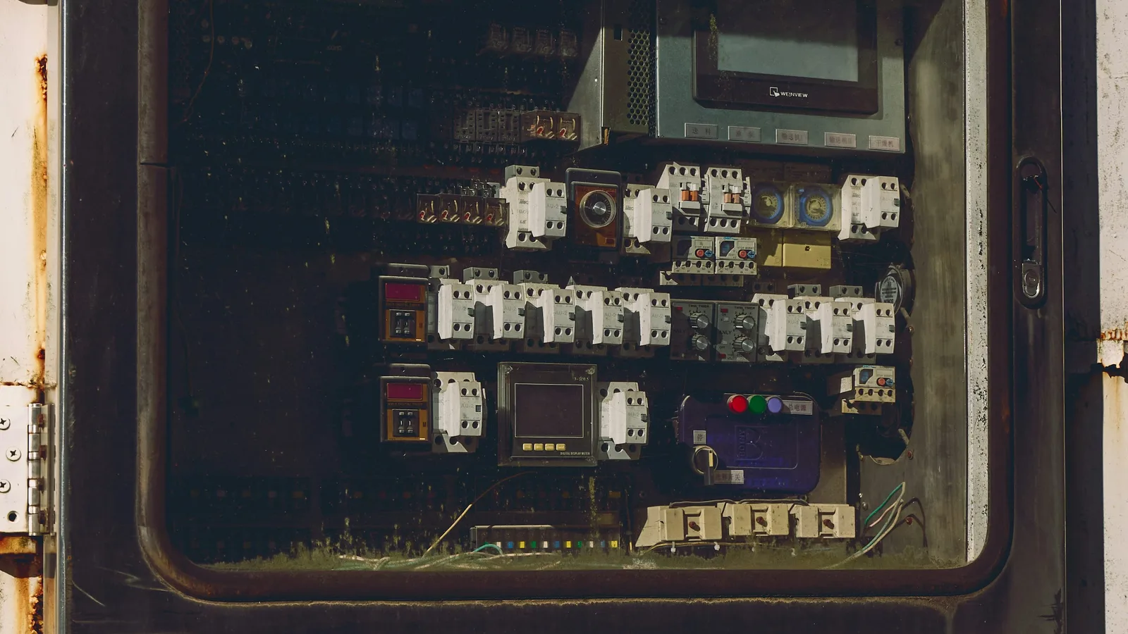
Control Panel Manufacturing: What Goes Into a Reliable Industrial Enclosure
CONTROL PANEL MANUFACTURING REQUIREMENTS
Control panel manufacturing combines electrical design, component selection, enclosure specification, panel control wiring, documentation, testing, and shipment.
A reliable industrial enclosure must provide:
- Correct environmental protection
- Adequate space for electrical components
- Defined power distribution
- Proper PLC and HMI integration
- Organized control wiring
- Accurate full-load ampere (FLA) calculations
- Thermal management
- Service access
- Complete schematic documentation
- Appropriate ratings and markings
The enclosure functions as the physical structure for the control system. The design must account for the equipment controlled, the installation environment, available power, motor loads, operating temperatures, maintenance access, and future service requirements.
Conveying Controls L.L.C. provides control system concept and design, procurement and specification services, schematic drawings, machine control wiring, conveyor control wiring, panel control wiring, and PLC- and HMI-based automation platforms. More than 35 years of experience support projects for manufacturing, warehousing, distribution, and material handling operations.
DEFINE THE APPLICATION
Control panel manufacturing begins with an application review.
Required information includes:
- Supply voltage
- Phase and frequency
- Motor horsepower
- Motor nameplate FLA
- Number of motors
- VFD and soft starter requirements
- PLC platform
- HMI requirements
- Safety circuit requirements
- Sensor and actuator counts
- Communication networks
- Enclosure location
- Ambient temperature
- Dust, moisture, washdown, or chemical exposure
- Available fault current
- Required disconnect configuration
- Required documentation
The application review establishes the panel architecture. Conveyor systems may require motor starters, variable frequency drives, photoeyes, proximity sensors, emergency stops, belt alignment switches, pull-cord switches, zero-speed switches, and operator stations.
Machine control panels may require additional I/O, safety relays, servo drives, pneumatic interfaces, recipe functions, and production data communication.
SELECT THE ENCLOSURE
The enclosure material, construction, and environmental rating must match the installation.
Common enclosure considerations include:
- Steel for general industrial applications
- Stainless steel for corrosion-prone or washdown environments
- Aluminum for weight-sensitive installations and selected electromagnetic interference applications
- Nonmetallic materials for specific chemical, moisture, or corrosion conditions
- Wall-mounted construction
- Free-standing construction
- Modular or bayed construction
- Separate operator control stations
- External disconnect handles
- Door-mounted HMIs and push buttons
NEMA and IP ratings identify environmental protection against conditions such as dust, water, and accidental contact. Typical industrial requirements may include Type 1, Type 12, Type 4, or Type 4X construction, depending on the installation.
The rating applies to the complete enclosure arrangement. Doors, hinges, latches, gaskets, cable entry points, operator devices, cooling equipment, and external fittings must maintain the specified protection.
For applicable industrial control panels, UL 508A provides construction and marking requirements for panels used in ordinary locations. Project requirements determine the applicable standard, listing, certification, and field approval process.
PLAN THE INTERNAL LAYOUT
Internal layout determines access, wiring paths, heat distribution, and serviceability.
A panel layout normally separates equipment into functional zones:
- Main disconnect and incoming power
- Branch circuit protection
- Motor starters and contactors
- Variable frequency drives
- Control transformers and power supplies
- PLC rack and I/O modules
- Safety control equipment
- Terminal blocks
- Network and communication devices
- Grounding and bonding points
- Spare capacity
High-power components require clearance for heat dissipation and maintenance. PLCs, communication devices, and analog signal equipment require separation from high-noise sources such as VFDs, contactors, and motor output wiring.
Mounting plates, DIN rails, wire duct, terminal blocks, and cable entry locations must be coordinated before assembly. Components must remain accessible after installation. Wire duct must allow conductor routing without excessive fill. Spare terminal points and unused DIN rail space can support later modifications.
CALCULATE FLA AND POWER REQUIREMENTS
FLA calculations establish the electrical requirements for the control panel.
The load list should identify:
- Motor nameplate FLA
- VFD input current
- Control transformer load
- Power supply load
- Heater load
- Solenoid load
- Auxiliary receptacle load
- Lighting load
- Continuous loads
- Spare capacity
FLA information supports the selection of:
- Main disconnect
- Feeder conductors
- Branch circuit conductors
- Circuit breakers
- Fuses
- Motor overload protection
- Contactors
- Terminal blocks
- Power distribution blocks
- Busbars
- VFDs
- Control transformers
- Power supplies
Motor FLA must be evaluated with starting requirements, overload protection, conductor sizing, and the equipment manufacturer’s instructions. VFD applications require review of both the drive input requirements and the connected motor.
The panel design must also address short-circuit current rating (SCCR). The SCCR must correspond to the selected components, protective devices, and available fault current at the installation.
Conveying Controls L.L.C. accommodates FLA calculations as part of the control system design process. Load information is incorporated into the electrical specifications and schematic documentation.
DESIGN THERMAL MANAGEMENT
Heat management is a control panel manufacturing requirement.
Heat sources may include:
- VFDs
- Power supplies
- Transformers
- Contactors
- Circuit protection devices
- Braking resistors
- Terminal connections
- Internal conductors
- Network equipment
Thermal design requires:
- Component heat-loss data
- Ambient temperature
- Enclosure dimensions
- Enclosure material
- Mounting location
- Internal component spacing
- Required internal operating temperature
- Cooling method
- Maintenance access
Available cooling methods include:
- Natural convection
- Filtered fans
- Fan-and-filter systems
- Heat exchangers
- Enclosure air conditioners
- Heaters for condensation control
- Thermostats and temperature switches
Sealed enclosures may require air conditioning or a heat exchanger when filtered ventilation would compromise the environmental rating. Fan filters require inspection and replacement intervals. Heaters may be required when ambient temperature changes create condensation risk.
VFDs and other high-loss devices must be positioned with manufacturer-required clearances. Wire duct and cable bundles must not block airflow. Temperature monitoring can provide an alarm input to the PLC or HMI when enclosure temperature approaches component limits.
ROUTE PANEL CONTROL WIRING
Panel control wiring must support electrical separation, identification, troubleshooting, and future service.
Recommended wiring practices include:
- Separate power and control wireways
- Separate VFD output wiring from PLC and analog signal wiring
- Route communication cables according to manufacturer requirements
- Cross incompatible wiring at 90 degrees when required
- Maintain conductor bend radius
- Use appropriately rated conductors
- Use ferrules or approved terminations where specified
- Torque terminals according to manufacturer requirements
- Bond doors and removable metal panels
- Provide protective earth connections
- Label conductors, terminals, and devices
- Match wire numbers to schematic drawings
Power wiring includes incoming feeders, motor circuits, VFD input conductors, VFD output conductors, and high-current distribution. Control wiring includes PLC I/O, interlocks, push buttons, sensors, analog signals, communication interfaces, and safety circuits.
The final wiring arrangement must be readable without removing unrelated conductors. Terminal numbering, wire labels, and device designations must correspond to the approved electrical schematics.
INTEGRATE PLC AND HMI PLATFORMS
PLC and HMI integration connects the electrical panel to the operating process.
PLC functions may include:
- Motor sequencing
- Conveyor interlocking
- Fault monitoring
- Sensor processing
- Safety status monitoring
- Start and stop control
- Production counting
- Alarm handling
- Network communication
- Data exchange with supervisory systems
HMI functions may include:
- Operator commands
- Motor status
- Fault indication
- Alarm history
- Speed adjustment
- Recipe or setup values
- Maintenance screens
- Manual jog controls
- System diagnostics
The HMI may be mounted on the enclosure door, on a remote operator station, or at a separate machine interface. Door-mounted equipment requires proper cutouts, sealing, mounting, labeling, and internal clearance.
PRODUCE SCHEMATIC DOCUMENTATION
Schematic drawings define the electrical system before and during panel assembly.
A complete drawing package may include:
- Title and revision information
- Incoming power diagrams
- Main disconnect details
- Branch circuit diagrams
- Motor starter diagrams
- VFD connections
- PLC layout and I/O diagrams
- HMI connections
- Safety circuit diagrams
- Terminal block schedules
- Field wiring diagrams
- Network diagrams
- Device lists
- Wire numbering
- Panel layout drawings
- Bill of materials
Documentation must identify component locations, conductor numbers, terminal points, field connections, and control logic interfaces.
For conveyor control wiring, drawings must show the relationship between motors, sensors, safety devices, operator stations, and PLC inputs and outputs. For machine control wiring, drawings must identify each controlled function and associated interlock.
VERIFY THE COMPLETED PANEL
Verification occurs before shipment and installation.
The inspection process may include:
- Component verification
- Nameplate verification
- Wire identification review
- Terminal torque inspection
- Grounding and bonding inspection
- Point-to-point continuity checks
- Input and output verification
- PLC configuration review
- HMI screen review
- Safety circuit verification
- Power distribution inspection
- Enclosure hardware inspection
- Schematic-to-panel comparison
- Documentation package review
Testing requirements depend on the project scope, customer specifications, applicable standards, and system integration requirements.
Conveying Controls L.L.C. provides end-to-end customer service from concept and specification through panel construction, documentation, and shipment. Exclusive shipping procedures support order protection during delivery.
CONTROL PANEL MANUFACTURING CHECKLIST
Use the following checklist for project review:
- Define application requirements
- Identify environmental conditions
- Select enclosure material
- Confirm NEMA or IP requirements
- Create the load list
- Complete FLA calculations
- Review SCCR requirements
- Select PLC and HMI platforms
- Design component layout
- Calculate heat load
- Select thermal management
- Route power and control wiring
- Produce schematic drawings
- Verify panel construction
- Test control functions
- Compile documentation
- Prepare shipment
CONTACT CONVEYING CONTROLS L.L.C.
Control panel manufacturing requires coordination between electrical design, procurement, component layout, panel control wiring, calculations, documentation, testing, and delivery.
Conveying Controls L.L.C. supports industrial automation projects for conveyor and material handling applications with more than 35 years of experience.
Services include:
- Full system concept and design
- Electrical control panel design
- PLC and HMI-based platforms
- Machine control wiring
- Conveyor control wiring
- Panel control wiring
- Schematic drawings
- Procurement and specification services
- FLA calculations
- Special project requests
- End-to-end customer service
- Exclusive shipping protection
Review Support
Contact Conveying Controls L.L.C.
SPECIFY. DESIGN. CALCULATE. WIRE. VERIFY.
© 2026 Conveying Controls L.L.C. All rights reserved.